

Turntable Cartridge Alignment Protractor PDF – Download & Print
Cartridge alignment protractor PDF: Introduction
A precise cartridge alignment is one of the most rewarding steps in turntable setup, and the right tool makes it simple. We developed the arc protractor generator on this page for the worldwide analog community: it creates a print-ready cartridge alignment protractor PDF tailored to your exact tonearm.
The tool is free and runs directly in your browser.
Alignment geometries such as Baerwald, Löfgren and Stevenson can be confusing, and protractor types even more so. For pivoted tonearms, an arc protractor generated for your exact pivot-to-spindle distance is the most accurate method available, and the 4 steps below take you from a single number to a precisely aligned cartridge.
1. Generate your arc protractor PDF
Generate your protractor directly on the arc protractor generator below. First choose your tonearm from the built-in list or enter your pivot-to-spindle distance. Then, select the alignment geometry: Löfgren A (Baerwald), Löfgren B, exact Löfgren C or Stevenson, as well as the DIN, IEC or Typical groove radii.
Once your settings are entered, simply click the button to download your alignment protractor PDF.
Löfgren A is our recommendation for balanced performance across the record. Differences between alignment geometries and DIN vs IEC groove radii are explained in the FAQ below.
If your tonearm is not in the built-in list, the section just below shows how to find your pivot-to-spindle distance.
Finding your tonearm pivot-to-spindle distance
If your tonearm was not in the list above, you can enter the distance yourself. Every arc protractor is built around this one number: the pivot-to-spindle distance of your tonearm. Manufacturers state it in the user manual, either directly or through the tonearm’s effective length and stylus overhang.
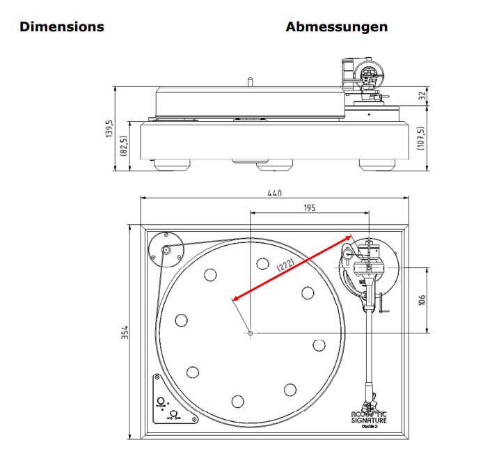
Acoustic Signature Double X 2019 User Manual.
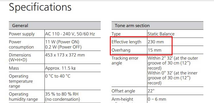
Technics SL-1200GR User Manual.
The generator above includes a built-in list of tonearms and turntables whose pivot-to-spindle distances are taken from the manufacturer’s own documentation and independently verified. If your tonearm is not in that list yet, or you would rather confirm the value yourself, your tonearm or turntable user manual is the authoritative source.
When the manual gives effective length and overhang instead, the calculation is:
Pivot-to-spindle distance = effective tonearm length − stylus overhang
For example, the Technics SL-1200GR pivot-to-spindle distance is: 230 mm (effective length) − 15 mm (overhang) = 215 mm. If no documentation is available, the distance can also be measured directly with a good ruler.
2. Print your arc protractor PDF
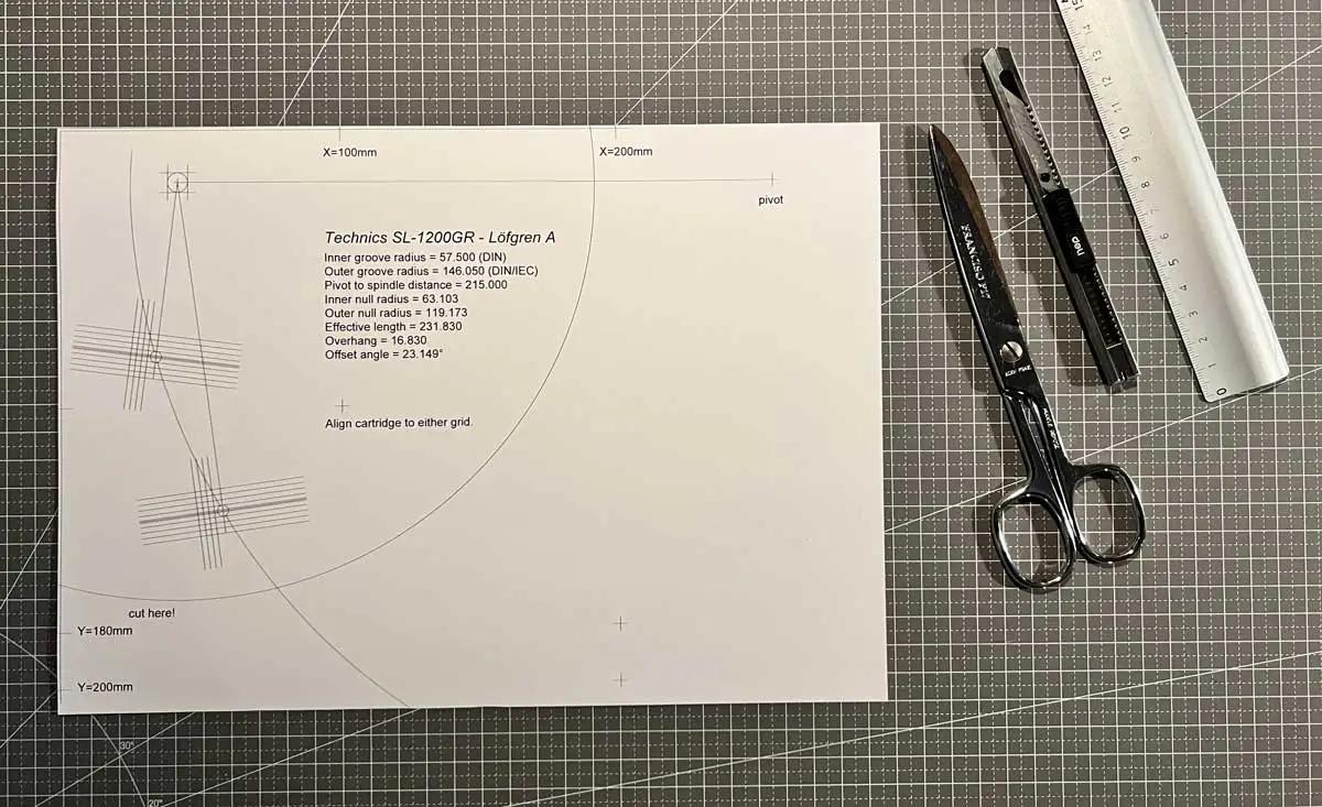
Example: printed protractor for the Technics SL-1200GR turntable.
For best results, print the PDF at 100% scale (no scaling, no “fit to page”) on a good printer. Photo paper is ideal: its smooth surface reduces stylus catching, and its weight adds stability.
Before using the template, check the calibration marks with a ruler. If your printer scales slightly, enter the measured values in the generator’s printer-correction fields and print again.
Cut the template along the curved record-edge line, and cut the pre-marked triangle at the spindle position. Press the paper gently over the spindle: the triangle flap centres the template snugly, with no freehand hole-cutting required.
3. Align your phono cartridge
1. Disable or set the anti-skating mechanism to zero.
2. Place a record on your turntable, then position the protractor on top of it.
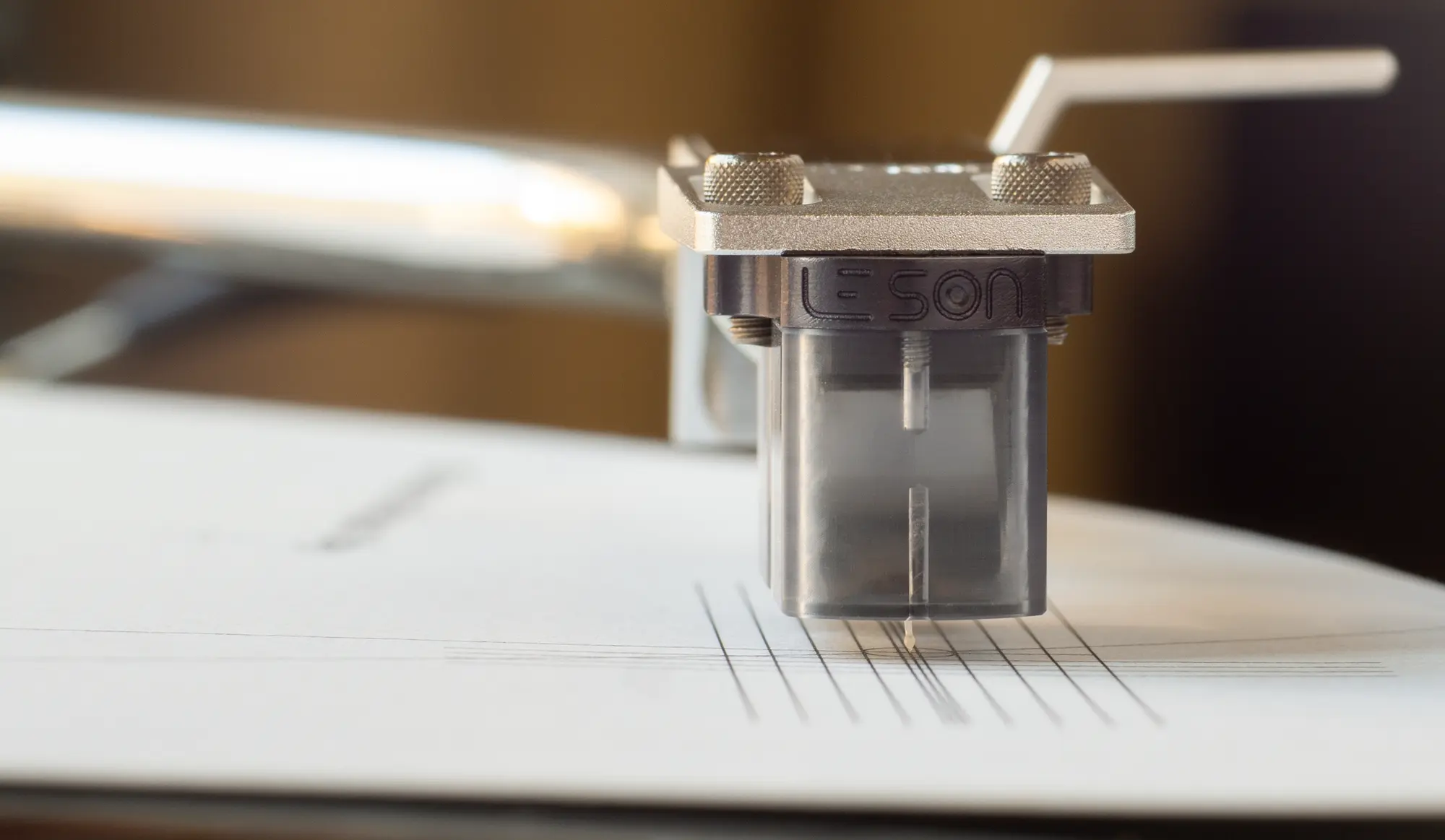
3. Lower the stylus at various points to ensure it traces the arc on the template:
- If the stylus touches the arc near the edge but misses near the spindle, move the cartridge forward.
- If it touches the arc near the spindle but overshoots near the edge, move the cartridge backward.
By adjusting the cartridge’s position in this manner, you should soon reach a point where the stylus tracks precisely along the arc, regardless of its position.
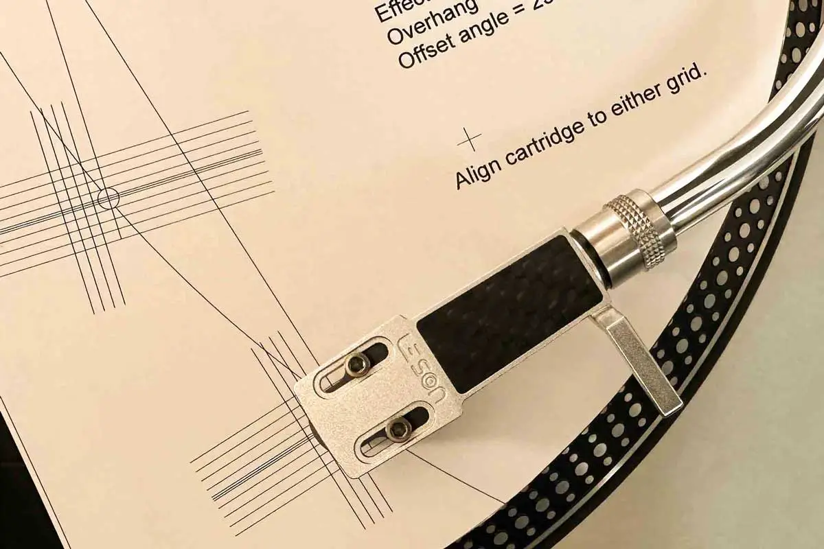
Once the stylus tracks the arc precisely, align the cartridge’s offset angle with either grid on the protractor. The grids sit at the two null points; the fine sight lines on each side of the centre line serve those who prefer aligning the cantilever rather than the cartridge body, and the perpendicular comb at the template’s front edge guards against misjudging the viewing angle.
If your cartridge cannot reach the required overhang or offset angle comfortably, the headshell may be limiting adjustment. Our guide to choosing a turntable headshell explains the main geometry and alignment points to check.
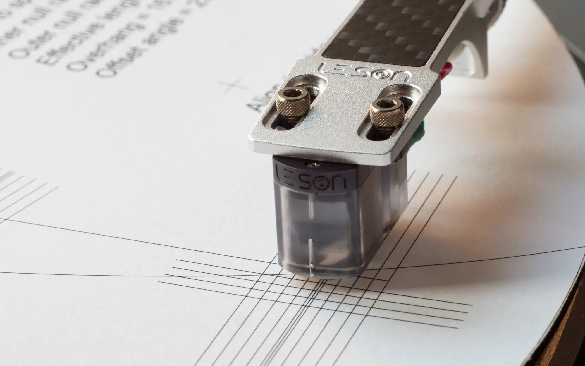
Here, the stylus of Le Son SL1 MKII Cartridge is spot on, and both the cartridge cantilever and body are aligned with the grid.
Once the stylus tracks the arc precisely and the cartridge body or cantilever aligns with either grid, congratulations, you’re all set!
Cartridge alignment protractor PDF: Conclusion
By following these three steps, you have brought tracking error down to the practical minimum for your tonearm: the quiet foundation of accurate, enjoyable vinyl playback.
Now, it is time to enjoy the sound of your vinyl records. If you are building a new setup around this alignment process, you can also explore our moving coil cartridges.
FREQUENTLY ASKED QUESTIONS
Choosing your alignment geometry
- Which alignment geometry should I choose: Löfgren A (Baerwald), Löfgren B, Löfgren C or Stevenson?
- What is Stevenson alignment, and when should I choose it?
- What is Löfgren C, and why do so few protractors offer it?
- What are null points, and why are there two?
- What is the difference between the DIN, IEC and Typical groove radii, and which should I choose?
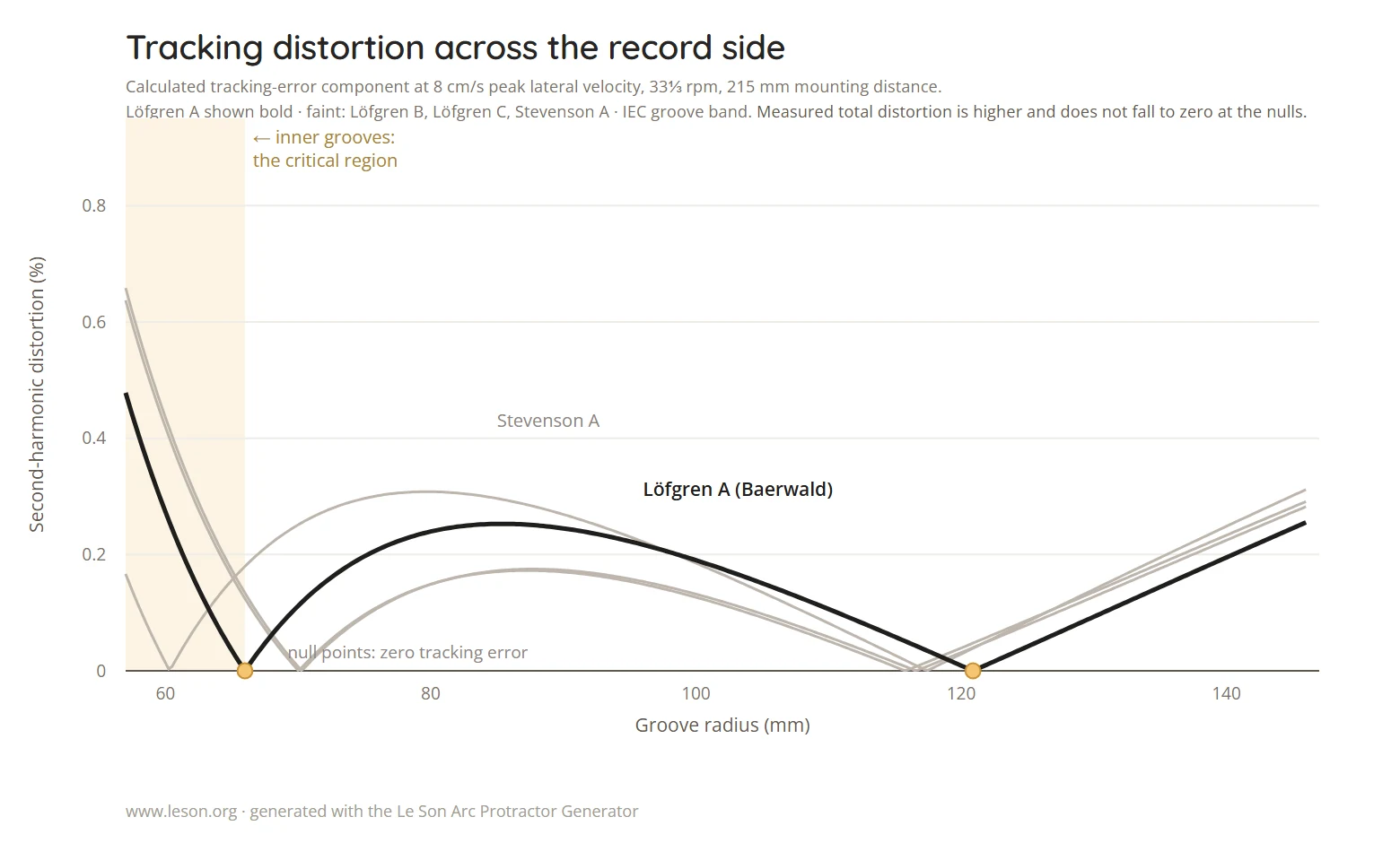
Löfgren A, also called Baerwald, is the right starting point for most systems. It equalises the three distortion peaks across the side, so no part of the record is favoured at the expense of another. Löfgren B and Löfgren C lower the average distortion instead, accepting a little more at the outer and inner edges. Stevenson places one of its two null points at the inner groove and suits listeners whose priority is the last tracks of a side. All four are available in the generator, and the chart it draws shows what each one trades.
Stevenson alignment sets one null point exactly at the inner groove radius, where the groove is most compressed and distortion is hardest to hide. Tracking error falls to zero there, at the cost of higher error across the rest of the side. It is the choice of listeners who care most about the final tracks. It also asks for the least overhang of the four geometries, which can help when a headshell offers little room for adjustment.
Löfgren C is the exact least-squares alignment: the geometry with the lowest average tracking distortion across the whole side. For decades only an approximation of it was published, and that approximation is what most tools label Löfgren B. Our generator computes the exact solution from the closed-form equations published by V. M. Jovanovic in the Journal of the Audio Engineering Society in 2022, alongside the three classical geometries.
A pivoted tonearm travels in an arc while the groove is a spiral, so the stylus can be exactly tangent to the groove at only a few radii. With the offset angle and overhang these geometries use, there are exactly two, and they are called null points. Everywhere else the tracking error is small but not zero. Choosing an alignment geometry is choosing where those two points sit.
They are three assumptions about where the music actually sits on your records. The alignment is optimised over that band, so the choice moves the null points and the overhang. IEC, 60.325 mm to 146.05 mm, is the international standard for the LP. DIN, 57.5 mm to 146.05 mm, is the older German standard, which allowed grooves to run closer to the label. Typical, 63 mm to 145 mm, is not a standard at all: it is a working convention for where the music on a normal commercial record starts and ends, since few records are cut to the limits their standard allows.
The trade is straightforward. A narrower band lowers the worst case inside it and raises the penalty for any record that runs past it. With Löfgren A on a 215 mm tonearm, at a reference level of 8 cm/s:
- DIN, 57.5 to 146.05 mm: peak distortion 0.28 percent across its own band, and 0.28 percent on a record whose groove runs in to 57.5 mm.
- IEC, 60.325 to 146.05 mm: 0.26 percent across its own band, 0.44 percent on that same record.
- Typical, 63 to 145 mm: 0.23 percent across its own band, 0.59 percent on that same record.
Choose IEC unless you know your collection well: DIN if you often play pre-1980s or densely cut records, Typical if your records end well clear of the label. The null radii depend only on this choice and the geometry, never on the length of your tonearm: 66.0 and 120.9 mm for IEC, 63.1 and 119.2 mm for DIN, 68.7 and 121.8 mm for Typical.
Your tonearm’s numbers
- What is the pivot-to-spindle distance, and how do I find it?
- What is overhang, and how is it related to effective length?
- My tonearm or turntable is not in the list. Can I still use the generator?
- I have an Ortofon, Audio-Technica or Denon cartridge. Do I need a protractor made for it?
It is the straight-line distance from the centre of the tonearm’s vertical pivot to the centre of the platter spindle, and it is the only measurement an arc protractor needs. Most tonearm and turntable manuals state it directly. When a manual gives effective length and overhang instead, subtract them: pivot-to-spindle distance = effective length − overhang. If nothing is published, measure it with a good steel rule, centre to centre.
Overhang is how far the stylus reaches past the spindle when the arm is swung over it. Effective length is the distance from the pivot to the stylus. The three figures are tied together: effective length = pivot-to-spindle distance + overhang. An arc protractor sets overhang for you. When the stylus follows the printed arc at every point, the overhang is correct by construction, and you never measure it directly.
Yes. The list is a convenience, not a limit. Enter your pivot-to-spindle distance by hand and the generator will produce a template for any pivoted tonearm between 60 mm and 400 mm. Your manual is the authoritative source, and where it gives effective length and overhang, subtract the two. If you have the manufacturer’s documentation for a model we do not cover yet, send it to us and we will verify it and add it.
No. Alignment geometry belongs to the tonearm, not to the cartridge: the same template is correct for every cartridge that fits your headshell. What differs from one cartridge to another is only how easily it reaches the required position. Mounting-hole spacing, body length and stylus position decide whether the headshell slots allow the overhang the geometry asks for.
Printing and accuracy
- How accurate is a printed arc protractor?
- How do I make sure my printer prints at true size?
- Which paper should I use, and should I laminate the template?
As accurate as the print. The geometry itself is exact: the null radii come from published closed-form equations, and the template is written as a true vector PDF, so nothing is lost to screen resolution or to rounding. We cross-checked our implementation against an independent implementation of the same geometries, and the agreement is at the limit of double-precision arithmetic, far below anything a printer or an eye can resolve. The variable is your printer, which is what the calibration marks on every template are for.
Print at 100 percent with scaling and “fit to page” switched off, then measure the two calibration spans on the sheet with a steel rule. If a measured span differs from the printed target, type what you measured into the generator’s printer-correction fields and print again. One pass is usually enough. The step is worth the minute: a one percent scaling error displaces the null points by about a millimetre. A4 and US Letter are both supported and the geometry is identical on either.
Photo paper is the best choice: its surface is smooth, so the stylus does not catch, and its weight keeps the sheet flat. Plain paper works if it is clean and unbent. Lamination adds durability at the cost of thickness, which lifts the stylus slightly above its playing height. If you laminate, use a thin film and measure the calibration spans again afterwards, since the heat can change the scale.
Doing the alignment
- How do I use an arc protractor?
- Should I align the cartridge body or the cantilever?
- Why must anti-skating be switched off, and how do I avoid a parallax error?
- The stylus follows the arc but the cartridge will not square up with the grid. What is wrong?
Set anti-skating to zero, place a record on the platter and the template over the spindle, then slide the cartridge in the headshell slots until the stylus rides on the printed arc along its whole length. Rotate the cartridge until its body or cantilever squares with either grid, then check the arc again. The three steps above cover each stage in detail.
Either. The template is drawn for both. The cantilever is what actually reads the groove, so it is the more exact reference, particularly if the stylus is not perfectly square in the body. The body is easier to judge and is what most listeners use, and on a well-made cartridge the two agree closely. The pair of fine lines flanking each grid’s centre line is spaced for a cantilever; the wider lines are there to square the sides of the body.
Anti-skating pulls the arm outward, which biases where the stylus settles and makes the arc reading unreliable. Set it to zero for the alignment and restore it, with the tracking force, once you are done. Parallax is the other common source of error: read the grid with one eye, directly above the stylus. The comb of perpendicular lines at the front edge of the template gives you a reference for a square viewing angle.
Usually nothing. The two adjustments are independent: slide for the arc, rotate for the grid, then re-check the arc, because rotating the cartridge moves the stylus a little. If it still will not square after two passes, the likely causes are a cantilever that is not straight in the body, mounting holes that limit rotation, or headshell slots too short for the overhang your geometry asks for. In the last case, a geometry with less overhang, or a different headshell, will resolve it.
Scope, limits and upkeep
- What is inner-groove distortion, and does alignment remove it?
- How often should I check my cartridge alignment?
- Does this work for 12-inch arms, underhung arms or linear trackers?
- Is the generator free, and does anything I enter leave my browser?
Inner-groove distortion is the rise in audible distortion towards the end of a side. Two causes combine: the groove velocity falls as the radius shrinks, so the same music is cut into less groove length, and the residual tracking error of a pivoted arm produces its largest distortion where the radius is smallest. Alignment cannot change the first. It minimises the second, and Stevenson addresses it directly by placing a null exactly at the inner groove.
Whenever the cartridge is fitted or refitted, after a retip or a rebuild, after the headshell has been off the arm, and after the turntable has been moved. Between those events there is little to drift, since the geometry is held by screws. A yearly check is reasonable, mainly to confirm that nothing has loosened.
It works for any pivoted tonearm with an offset headshell, whether 9, 10 or 12 inch, because only the pivot-to-spindle distance changes. It does not apply to linear-tracking arms, which stay tangent to the groove and have no null points to set. Underhung arms without an offset angle follow a different geometry with a single null point, and the generator does not produce templates for them.
It is free, with no account and no email address required. Everything runs in your browser: the figures you enter and the PDF you create stay on your computer, and once the page has loaded the generator needs no connection.
If there is anything else you would like to know or if you need further assistance, feel free to CONTACT US.
Our team is dedicated to providing you with timely and helpful responses, usually within 24 hours.
L’Or du Son
The analog sound newsletter
A monthly selection of analog news, gear reviews, record releases and music discoveries, curated to keep you inspired and connected to the world of analog sound.
About this tool
What it does. Draws an arc protractor for your tonearm, ready to print, to set the cartridge’s overhang and offset angle. Choose your tonearm from the list or enter its pivot-to-spindle distance, pick an alignment, and download the PDF. It also shows the tracking error of each alignment across the record.
How it works. It uses the published formulas for the four common alignments: Löfgren A (also known as Baerwald), Löfgren B, Löfgren C in its exact form (Jovanovic, 2022) and Stevenson A, on the DIN, IEC or Typical groove radii. Its results were checked against Conrad Hoffman’s TemplateGen and Graeme Dennes’ tonearm geometry workbook.
Limits. A protractor is only as accurate as its print: print at 100% scale and measure the scale marks on the sheet before use. The chart shows the error the geometry itself causes, calculated, not distortion measured from a record.
Example. For a tonearm with a 215 mm pivot-to-spindle distance, Löfgren A on IEC radii gives 17.82 mm overhang, a 23.66° offset angle, and null points at 66.00 mm and 120.89 mm from the spindle.
Made by. Le Son, Shanghai. Built in July 2026, updated in September 2026.
How to cite. Le Son, Arc Protractor Generator, leson.org/turntable-cartridge-alignment-protractor-pdf-download-print/

Gregory de Richemont
Gregory de Richemont is the founder of Le Son, where high-fidelity sound is approached as both a technical pursuit and an emotional experience. After a career in international business, he followed a more personal path into analog playback, music and craftsmanship. His work is dedicated to listening experiences that do more than impress: they create a deeper connection with music. Learn more on our About page.