Understand phono cartridges: Introduction
A phono cartridge is the point where the physical groove in a record becomes an electrical signal. It is one of the most delicate and influential parts of an analog system, because it must read microscopic groove modulations accurately while treating the record with care.
This guide explains the main principles that shape cartridge performance: generator type, stylus behavior, tracking force, effective tip mass, compliance, resonance, distortion, and wear. Its purpose is not only to define terms, but to help the reader understand why cartridge design matters in real listening and real setup.
Interfaces
A cartridge never works in isolation. Its final performance depends on three interfaces: the record, the tonearm, and the amplifier or phono stage. Each of them affects what the cartridge can do, and each can either support or limit the result.
The record is the source of the mechanical information. Its groove shape, modulation, condition, and pressing quality all influence what the stylus is asked to trace.
The tonearm provides the cartridge with its mechanical working environment. Effective mass, bearing quality, geometry, and stability all affect tracking, resonance, and distortion.
The amplifier or phono stage provides the electrical environment. Gain, loading, and the cable path between tonearm and phono stage all influence how the cartridge behaves and how faithfully its signal is received.
Recorded information
A record groove contains an extraordinary amount of information in a very small space. The cartridge stylus must trace that information accurately as the record turns, converting microscopic mechanical movement into an electrical signal.
In a stereo record, the two groove walls carry the left and right channel information at different angles, as shown in Fig. 1. The stylus touches both walls at once, and its motion reflects the musical information cut into the groove.
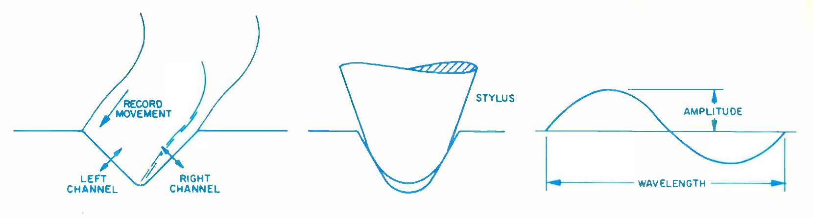
Fig. 1 – Stereo signal in record groove, fit of stylus in groove, and relation of amplitude and wavelength.
This is important because groove behavior changes with frequency and position on the record. Low frequencies usually involve larger groove excursions, while high frequencies involve smaller but faster movements.
As the stylus approaches the inner grooves, the physical wavelength becomes shorter, which increases the demands on tracing accuracy. The cartridge is therefore dealing not with a static shape, but with continuously changing groove geometry and acceleration.
In other words, accurate playback depends on the stylus being able to follow both large slow movements and very small fast ones, while remaining stable and gentle to the record.
Magnetic transducers
Most serious phono cartridges in use today are based on magnetic transducer principles. In simple terms, stylus motion causes a change in magnetic flux, and that change generates the electrical signal sent to the phono stage.
The three main magnetic approaches are moving coil, moving magnet, and moving iron. In each case, the goal is the same: convert stylus motion into electrical energy as accurately as possible.
What matters most is not the label alone, but how well the stylus follows the groove, how cleanly that movement is transferred through the cantilever and generator, and how consistently the system behaves under real playback conditions. The sections that follow explain the design factors that most strongly affect that outcome.

Fig. 2 – The three basic types of magnetic transducers.
- The moving coil (MC) transducer, also called dynamic, has a fixed magnet flux in the air gap. The flux relative to the coil changes, however, as the coil in the air gap connected to the stylus moves, inducing a voltage.
- In the moving magnet (MM) transducer, the magnet is connected to the stylus and located in the air gap. Flux in the magnetic circuit is changed directly as the distance of the magnet to the poles changes, inducing a voltage in the coils wound on the iron.
- The moving iron (MI) transducer, also called variable reluctance or induced magnet, changes flux by altering the magnetic path in the air gap, as the iron armature moves. The coils are wound on iron poles, which form part of the magnetic circuit.
In order to get sufficient output, the size, materials, and layout of the elements in the three cases will not be the same. But none of the principles, in themselves, have any performance advantage over the others. Performance will depend on how accurately the stylus can be made to follow groove modulation, how accurately stylus movement can be transferred to the armature, and how accurately armature movement can be converted to a change in flux.
The sections that follow illustrate some of the important design and performance parameters; some aspects of a major problem in record reproduction, record and stylus wear, will also be covered.
Vertical tracking force
Terms such as stylus pressure or tracking weight are also used to denote the Vertical Tracking Force (VTF). This force is set on the tonearm to ensure contact between the stylus and the groove. The stylus makes contact with the groove wall in two small areas, the size of which depends on the shape of the diamond, as shown in the diagram. Force per unit of contact area is pressure, and in this case will be called the stylus pressure generated by the VTF.
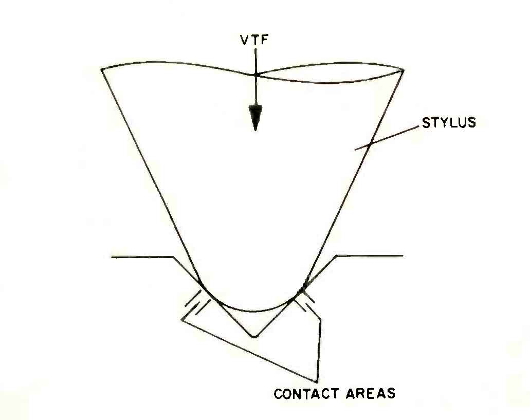
Fig. 3 – Vertical tracking force and contact area.
Vinyl plastic, of which modern records are made, is not completely rigid and deforms under pressure. Like other plastics, it has two main zones of deformation, although there is no sharp transition between them. At low pressure, up to point A in Fig. 4, deformation is said to be elastic, and the vinyl returns to its original shape when the pressure is removed. For higher pressures, such as at B, C, and D, the material is deformed progressively deeper into the plastic region, so that it only partially returns to its original shape when pressure is removed.
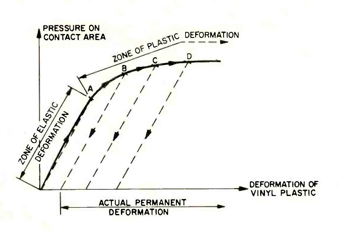
Fig. 4 – Deformation for various pressures exerted by stylus.
Thus, for any reasonable VTF, stylus pressure is comparatively low, and while the groove deforms under the stylus, it returns to its original shape after the stylus has passed. But for VTF above a certain level, stylus pressure is so high that plastic deformation occurs and the vinyl suffers permanent damage. For unmodulated grooves, this point is not reached until the VTF is well above 30 mN (approx. 3 grams).
But when grooves are modulated the picture changes. It will be shown that the stylus pressure on the record changes with modulation, giving wear depending on whether the vinyl remains within the elastic region or if it is deformed into the plastic region.
A misconception about VTF is that the wear is sometimes directly attributed to this VTF factor, but wear which can only be caused by friction between the stylus and the groove walls. If the stylus is correctly shaped and well polished, wear is negligible. However, if the stylus is badly polished, worn, or damaged, wear can increase dramatically. When wear or damage is suspected, professional retipping may be the most sensible next step, subject to inspection.
Effective tip mass
Effective Tip Mass, or ETM, is one of the most important ideas in cartridge design. It describes the apparent mass of the moving stylus system as seen at the stylus tip. In practice, it reflects the combined effect of the stylus, cantilever, armature, and their geometry.
Lower ETM helps the stylus respond more easily to rapid groove accelerations, especially at high frequencies. Higher ETM makes that harder, which can increase mistracking, wear, and distortion when the groove becomes demanding.
This is why cartridge design is always a balance. The designer wants low moving mass, but must also maintain sufficient output, structural integrity, clearance, and mechanical stability. ETM is therefore not an isolated number, but a central design constraint with direct consequences for tracking and record care.
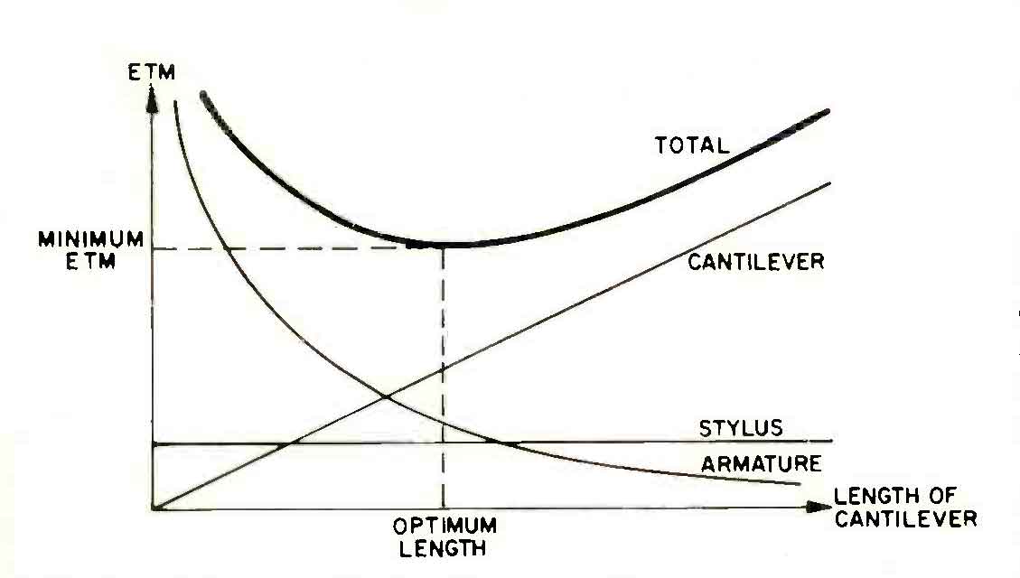
Fig. 5 – Effect on effective tip mass of increasing various cartridge parameters.
It can be seen that as cantilever length increases, the contribution of the armature decreases. At the same time the contribution of the cantilever increases, while that of the stylus remains constant. The sum of the factors shows a minimum value at a particular cantilever length, which is optimum for that armature and that kind of cantilever. If we wish to alter the ETM or if the cantilever length found is unsuitable, the design must be changed and a new optimum for the combination found.
At the same time mimimum voltage output must be provided, and this is also related to the size of the armature and the movement transferred from the stylus to the armature. In addition, the cantilever length must be adequate for clearance between the cartridge and the record. Because these factors conflict with low cartridge ETM, this is a very fundamental and difficult parameter for the designer, one that sets its mark on the rest of the design and on overall performance.
The need for low ETM follows from Newton’s first law of motion, which says F = M x A, where F is force, M is mass, and A is acceleration. If we find a mass, M, which for a given force, F, accelerates at the same rate, A, as the moving parts of our cartridge, then this mass is the ETM of the cartridge.
The ETM can be thought of as being concentrated at the stylus tip, and as the exact equivalent of all masses of the individual moving parts for forces applied at the stylus tip.
Newton’s law now tells us that for any given acceleration on the record, the force between the record and the stylus is proportional to the ETM. Of course, acceleration on the record is not constant, and we also know that for the ETM of a given cartridge, that force is proportional to the acceleration.
Consider the stylus at the bottom of the groove modulation. A force is provided by the record to move the stylus, defined by the ETM and the acceleration at that point. When the stylus reaches the top of the modulated groove and attempts to go down, there is no force available in the record to maintain contact. This is provided externally by the VTF, which must be at least as large as the force defined by the ETM and the largest acceleration on the record. If this VTF is not provided or it is too low, the stylus will momentarily loose contact with the record, but will return further down the groove causing severe damage at the point of contact (see Fig. 6 A and B).
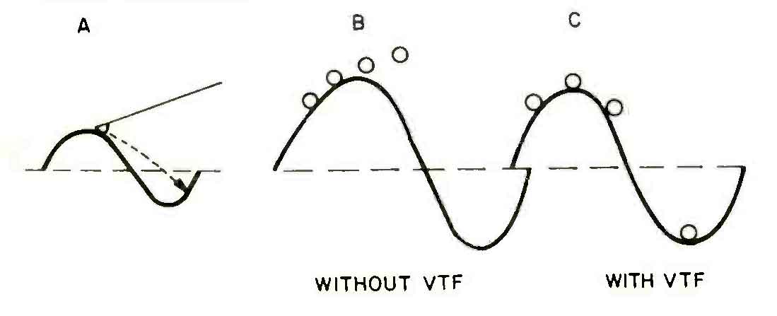
Fig. 6 – Motion of stylus tip with and without vertical tracking force.
Even when VTF is adequate, the pressure at the bottom of the groove is now due to the sum of the force required to accelerate the ETM and the VTF, which is constant. The larger the ETM, the larger the combined force, and the resultant pressure can easily be sufficiently high to cause plastic deformation and permanent damage.
Since high acceleration occurs only with relatively high frequencies, low ETM is important only at the high end of the recorded spectrum. Wear caused by high ETM will occur on a record with a large high frequency content, where distortion due to wear is most audible.
Compliance
Compliance describes how easily the stylus assembly moves in response to groove modulation. In simple terms, it reflects how soft or stiff the cartridge suspension is.
This matters because the suspension must do two things at once: allow the stylus to follow the groove accurately, and return it to a stable working position. If compliance is too low, the suspension resists movement too strongly and tracking can suffer, especially on larger low-frequency modulations. If compliance is too high, control can become unstable and the cartridge may be more difficult to match properly to the tonearm.
Compliance must therefore be understood together with tonearm mass, tracking force, and resonance behavior. On its own, it tells only part of the story. In practice, good performance depends on the whole mechanical match.
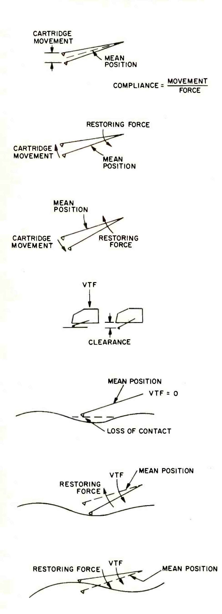
Fig. 7 – Illustrations of the effects of compliance on stylus motion.
If tracking force is too low relative to the restoring force of the suspension, the stylus may lose contact with the groove and then strike it again further along. That kind of mistracking can cause severe record damage.
At the same time, a suspension that is too stiff can also create excessive force when large groove excursions occur. In that case, the combination of restoring force and tracking force may push groove pressure beyond a safe range.
This is why compliance is not a theoretical curiosity. It directly affects low-frequency tracking, stability, and record care. In practice, compliance must be judged together with tracking force and tonearm mass, not on its own.
Resonance
Resonance appears whenever mass and elasticity interact, and a phono cartridge system contains several such interactions. In the simplest sense, resonance is the frequency at which a system begins to store and release energy instead of merely following the input in a controlled way.
In analog playback, resonance matters because it can greatly increase movement at certain frequencies. When that happens, the stylus, cantilever, or tonearm may move more than intended, which can lead to coloration, mistracking, instability, or audible distortion.
Not all resonance is automatically harmful, but uncontrolled resonance is always a problem. Good cartridge and tonearm design aim to place resonant behavior in sensible regions and to control its amplitude through mass, compliance, and damping.
The diagrams below illustrate the basic principle before we apply it to the cartridge and tonearm system itself.
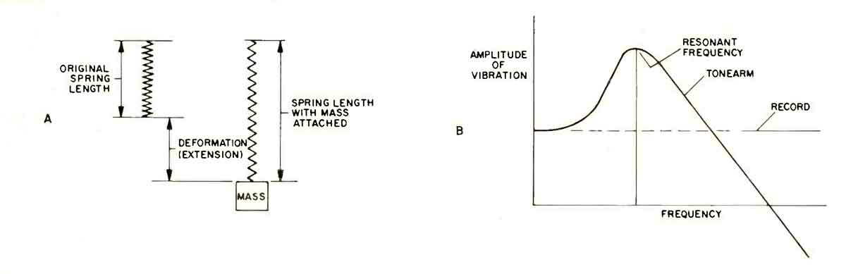
Fig. 8 – A: deformation of a spring by adding mass; B: change in amplitude of vibration at resonant frequency.
Tonearm
A cartridge can only perform as well as the tonearm allows. The tonearm must hold the cartridge in a stable geometric relationship to the groove while still allowing the stylus to move freely as the record demands.
Its bearing quality, effective mass, rigidity, and resonance behavior all matter. Too much friction, poor resonance placement, or a weak mechanical match can disturb stylus motion, alter tracking force in practice, and increase distortion or wear.
This is why cartridge matching is never only about the cartridge itself. A good cartridge in the wrong arm may work, but it may not work well. The best results come from a tonearm and cartridge whose mass, compliance, and intended behavior are genuinely compatible.
Frequency response and damping
The ETM of a cartridge supplies the mass for another resonance system. Together with the elasticity of the record material, which acts as a spring, there is a resonance which in most modern cartridges lies between 15 and 50 kHz. This may be called the high frequency resonance of the cartridge.
Since the elasticity (or compliance) of the record is essentially constant, the resonant frequency depends on cartridge ETM alone. The lower the ETM, the higher the resonant frequency. The reasoning applied to any resonance is also valid here. At and around the resonant frequency, there will be out-of-phase effects which leads to increased relative vibration of the armature compared to the amplitude of the groove modulation. This gives a peak in the frequency response curve.
Further, due to the out-of-phase movement, stylus pressure acting on the record will vary, and at points where pressure is maximum and minimum, the stylus may cause plastic deformation or loss of contact with the groove leading to damage on making contact again. This is the most prevalent form of wear and distortion for cartridges in general. In cartridges with high ETM, it is possible to measure the effect as a “footprint” in a frequency response curve due to wear at the resonant frequency after a single playing of a record. The high frequency resonance results in a peak at the upper end of the frequency response curve of the cartridge, after which response falls sharply. A square wave test shows ringing on the horizontal sections of the curve.
To avoid these effects, the resonance is usually damped, using the suspension elastomer as the damping medium. Careful choice of the material, size, shape, and position of the elastomer is required to match the damping properties to the high frequency resonance, to give the necessary compliance, and the optimum frequency response characteristics.
Distortion
Distortion appears when the electrical output of the cartridge no longer corresponds faithfully to the information in the groove. Its causes can be mechanical, magnetic, or electrical, and in practice several of them often overlap.
The most important mechanical causes usually come first: mistracking, resonance, poor armature control, precession, cantilever behavior, or setup errors that move the generator away from its intended working position. Magnetic and electrical factors also matter, but many audible problems begin with mechanical instability.
Other mechanical causes can also contribute to distortion. These include cantilever resonance, precession, excessive compliance in the wrong context, and tracing differences between the playback stylus and the cutting stylus. Some of these effects are subtle, but together they can blur timing, harden tone, or reduce clarity.
Magnetic causes are generally smaller in well-designed cartridges, but they still exist. If armature motion does not produce a perfectly linear change in magnetic flux, distortion can result. In practice, modern cartridge design keeps these effects under much better control than the larger mechanical problems discussed above.
Electrical behavior also matters. A cartridge does not feed the phono stage in isolation. Coil impedance, cable capacitance, phono-stage input characteristics, gain, and loading all influence the final result. In some systems, these interactions can audibly affect openness, tonal balance, control, and noise.
This is especially important with moving coil cartridges, which often have low output and require either a suitable MC phono stage or an appropriate step-up transformer. In these cases, system matching is not a detail. It is part of the cartridge’s real performance.
Crosstalk
If the signal from one of the channels of a stereo pair breaks through into the other, the phenomenon is called crosstalk. The main cause is that the axes of the generating system are not parallel to, the axes of the signal recorded in the grooves. This can be due to manufacturing tolerances or can be inherent in the transducer design, which may be sensitive to vibrations in the opposite channel. A small amount of crosstalk will not normally be audibly unpleasant, as it will only result in a minor reduction in stereo separation.
It becomes unpleasant if distortion products are present in the crosstalk signal. This can occur for any of the reasons given for distortion especially cantilever resonance, non-centered armature, lateral movement of the point of rotation due to excessive compliance, or a precession. Other causes of crosstalk are incorrect mounting of the cartridge in the tonearm relative to the record and resonances in the tonearm itself.
Understand phono cartridges: Conclusion
Designing a great phono cartridge means balancing many variables that do not always point in the same direction. Output, tracking ability, moving mass, compliance, damping, resonance behavior, record care, and long-term musical balance all have to be considered together.
A cartridge may excel in one isolated area and still be less convincing overall. The most meaningful designs are those that remain coherent across many kinds of music, track securely, preserve records respectfully, and deliver a satisfying balance of clarity, tone, timing, and stability.
That is why phono cartridges are best understood not through one specification alone, but through the relationship between design choices, setup, and listening results. To see how these principles are applied in practice, explore our moving coil cartridges.
Credits:
Author: S.K. Pramanik
Audio R&D Engineer – Bang & Olufsen – Struer, Denmark.
Paper originally published in Audio Vol.63 (March, 1979).
L’Or du Son
The analog sound newsletter
A monthly selection of analog news, gear reviews, record releases and music discoveries, curated to keep you inspired and connected to the world of analog sound.
Gregory de Richemont
Gregory de Richemont is the founder of Le Son, where high-fidelity sound is approached as both a technical pursuit and an emotional experience. After a career in international business, he followed a more personal path into analog playback, music and craftsmanship. His work is dedicated to listening experiences that do more than impress: they create a deeper connection with music. Learn more on our About page.